trackers Package
tracker Module
Module containing all the elements to track the RF frequency, voltage, phase, and the beam coordinates in phase space.
- Authors
Helga Timko, Alexandre Lasheen, Danilo Quartullo
-
class
blond.trackers.tracker.FullRingAndRF(RingAndRFSection_list)¶ Bases:
objectDefinition of the full ring and RF parameters in order to be able to have a full turn information (used in the hamiltonian for example).
-
RingAndRFSection_list¶ List of the total RingAndRFSection objects
-
potential_well¶ Total potential well in [V]
-
potential_well_coordinates¶ Total potential well theta coordinates in [rad]
-
potential_well_generation(turn=0, n_points=100000.0, main_harmonic_option='lowest_freq', dt_margin_percent=0.0, time_array=None)¶ Method to generate the potential well out of the RF systems. The assumption made is that all the RF voltages are averaged over one turn. The potential well is then approximated over one turn, which is not the exact potential. This approximation should be fine enough to generate a bunch (the mismatch should be small and damped fast enough). The default main harmonic is defined to be the lowest one in frequency. The user can change this option if it is not the case for his simulations (other options are: ‘highest_voltage’, or inputing directly the value of the desired main harmonic). A margin on the time array can be applied in order to be able to see the min/max that might be exactly on the edges of the frame (by adding a % to the length of the frame, this is set to 0 by default. It assumes also that the slippage factor is the same in the whole ring.
-
ring_circumference¶ Ring circumference in [m]
-
ring_radius¶ Ring radius in [m]
-
track()¶ Function to loop over all the RingAndRFSection.track methods
-
-
class
blond.trackers.tracker.RingAndRFTracker(RFStation, Beam, solver='simple', BeamFeedback=None, NoiseFeedback=None, CavityFeedback=None, periodicity=False, interpolation=False, Profile=None, TotalInducedVoltage=None)¶ Bases:
objectClass taking care of basic particle coordinate tracking for a given RF station and the part of the ring until the next station, see figure.
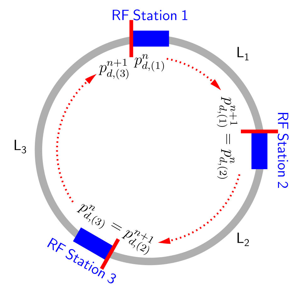
The time step is fixed to be one turn, but the tracking can consist of multiple RingAndRFTracker objects. In this case, the user should make sure that the lengths of the stations sum up exactly to the circumference or use the FullRingAndRF object in order to let the code pre-process the parameters. Each RF station may contain several RF harmonic systems which are considered to be in the same location. First, the energy kick of the RF station is applied, and then the particle arrival time to the next station is updated. The change in RF phase, voltage, and frequency due to control loops is tracked as well.
- Parameters
RFStation (class) – A RFStation type class
counter ([int]) – Inherited from
input_parameters.rf_parameters.RFStation.counterlength_ratio (float) – Inherited from
input_parameters.ring.Ring.length_ratiosection_length (float) – Inherited from
input_parameters.ring.Ring.section_lengtht_rev (float) – Inherited from
input_parameters.ring.Ring.t_revn_rf (float) – Inherited from
input_parameters.rf_parameters.RFStation.n_rfbeta (float) – Inherited from
input_parameters.ring.Ring.betacharge (float) – Inherited from
input_parameters.ring.Ring.Particle.chargeharmonic (float array) – Inherited from
input_parameters.rf_parameters.RFStation.harmonicvoltage (float array) – Inherited from
input_parameters.rf_parameters.RFStation.voltagephi_noise (float array) – Inherited from
input_parameters.rf_parameters.RFStation.phi_noisephi_modulation (2-tuple of float array) – Inherited from
input_parameters.rf_parameters.RFStation.phi_modulationphi_rf (float array) – Inherited from
input_parameters.rf_parameters.RFStation.phi_rfphi_s (float array) – Inherited from
input_parameters.rf_parameters.RFStation.phi_salpha_0 (float array) – Inherited from
input_parameters.ring.Ring.alpha_0alpha_1 (float array) – Inherited from
input_parameters.ring.Ring.alpha_1alpha_2 (float array) – Inherited from
input_parameters.ring.Ring.alpha_2eta_0 (float array) – Inherited from
input_parameters.ring.Ring.eta_0eta_1 (float array) – Inherited from
input_parameters.ring.Ring.eta_1eta_2 (float array) – Inherited from
input_parameters.ring.Ring.eta_2alpha_order (float array) – Inherited from
input_parameters.ring.Ring.alpha_orderacceleration_kick (float array) – Inherited from
input_parameters.ring.Ring.delta_Eand multiplied by -1Beam (class) – A Beam type class
solver (str) – Type of solver used for the drift equation; use ‘simple’ for 1st order approximation and ‘exact’ for exact solver
BeamFeedback (class (optional)) – A BeamFeedback type class, beam-based feedback on RF frequency; default is None
NoiseFeedback (class (optional)) – A NoiseFeedback type class, bunch-length feedback on RF noise; default is None
periodicity (bool (optional)) – Option to switch periodic solver on/off; default is False (off)
interpolation (bool (optional)) – Option to use sliced and interpolated voltage for the kicker; default is False
-
drift(beam_dt, beam_dE, index)¶ Function updating the particle arrival time to the RF station (drift). If only the zeroth order slippage factor is given, ‘simple’ and ‘exact’ solvers are available. The ‘simple’ solver is somewhat faster. Otherwise, the solver is automatically ‘exact’ and calculates the frequency slippage up to second order. The corresponding equations are (nb: the n indices correspond to the turn number):
\[\Delta t^{n+1} = \Delta t^{n} + \frac{L}{C} T_0^{n+1} \left[ \left(1+\sum_{i=0}^{2}{\alpha_i\left(\delta^{n+1}\right)^{i+1}}\right) \frac{1+\left(\Delta E/E_s\right)^{n+1}}{1+\delta^{n+1}} - 1\right] \quad \text{(exact)}\]\[\Delta t^{n+1} = \Delta t^{n} + \frac{L}{C} T_0^{n+1} \left(\frac{1}{1 - \eta(\delta^{n+1})\delta^{n+1}} - 1\right) \quad \text{(legacy)}\]\[\Delta t^{n+1} = \Delta t^{n} + \frac{L}{C} T_0^{n+1}\eta_0\delta^{n+1} \quad \text{(simple)}\]The relative momentum needs to be calculated from the relative energy and is obtained as follow:
\[\delta = \sqrt{1+\beta_s^{-2}\left[\left(\frac{\Delta E}{E_s}\right)^2 + 2\frac{\Delta E}{E_s}\right]} - 1 \quad \text{(exact)}\]\[\delta = \frac{\Delta E}{\beta_s^2 E_s} \quad \text{(simple, legacy)}\]
-
kick(beam_dt, beam_dE, index)¶ Function updating the particle energy due to the RF kick in a given RF station. The kicks are summed over the different harmonic RF systems in the station. The cavity phase can be shifted by the user via phi_offset. The main RF (harmonic[0]) has by definition phase = 0 at time = 0 below transition. The phases of all other RF systems are defined w.r.t.to the main RF. The increment in energy is given by the discrete equation of motion:
\[\Delta E^{n+1} = \Delta E^n + \sum_{k=0}^{n_{\mathsf{rf}}-1}{e V_k^n \sin{\left(\omega_{\mathsf{rf,k}}^n \Delta t^n + \phi_{\mathsf{rf,k}}^n \right)}} - (E_s^{n+1} - E_s^n)\]
-
rf_voltage_calculation()¶ Function calculating the total, discretised RF voltage seen by the beam at a given turn. Requires a Profile object.
-
track()¶ Tracking method for the section. Applies first the kick, then the drift. Calls also RF/beam feedbacks if applicable. Updates the counter of the corresponding RFStation class and the energy-related variables of the Beam class.
utilities Module
Utilities to calculate Hamiltonian, separatrix, total voltage for the full ring.
- Authors
Danilo Quartullo, Helga Timko, Alexandre Lasheen
-
blond.trackers.utilities.hamiltonian(Ring, RFStation, Beam, dt, dE, total_voltage=None)¶ Single RF sinusoidal Hamiltonian. For the time being, for single RF section only or from total voltage. Uses beta, energy averaged over the turn. To be generalized.
-
blond.trackers.utilities.is_in_separatrix(Ring, RFStation, Beam, dt, dE, total_voltage=None)¶ Function checking whether coordinate pair(s) are inside the separatrix. Uses the single-RF sinusoidal Hamiltonian.
- Parameters
Ring (class) – A Ring type class
RFStation (class) – An RFStation type class
Beam (class) – A Beam type class
dt (float array) – Time coordinates of the particles to be checked
dE (float array) – Energy coordinates of the particles to be checked
total_voltage (float array) – Total voltage to be used if not single-harmonic RF
- Returns
True/False array for the given coordinates
- Return type
bool array
-
blond.trackers.utilities.minmax_location(x, f)¶ Function to locate the minima and maxima of the f(x) numerical function.
-
blond.trackers.utilities.phase_modulo_above_transition(phi)¶ Projects a phase array into the range -Pi/2 to +3*Pi/2.
-
blond.trackers.utilities.phase_modulo_below_transition(phi)¶ Projects a phase array into the range -Pi/2 to +3*Pi/2.
-
blond.trackers.utilities.potential_well_cut(time_potential, potential_array)¶ Function to cut the potential well in order to take only the separatrix (several cases according to the number of min/max).
-
blond.trackers.utilities.separatrix(Ring, RFStation, dt)¶ Function to calculate the ideal separatrix without intensity effects. For single or multiple RF systems. For the time being, multiple RF sections are not yet implemented.
- Parameters
Ring (class) – A Ring type class
RFStation (class) – An RFStation type class
dt (float array) – Time coordinates the separatrix is to be calculated for
- Returns
Energy coordinates of the separatrix corresponding to dt
- Return type
float array
-
blond.trackers.utilities.synchrotron_frequency_distribution(Beam, FullRingAndRF, main_harmonic_option='lowest_freq', turn=0, TotalInducedVoltage=None, smoothOption=None)¶ Function to compute the frequency distribution of a distribution for a certain RF system and optional intensity effects. The potential well (and induced potential) are not updated by this function, thus it has to be called after the potential well (and induced potential) generation.
If used with induced potential, be careful that noise can be an issue. An analytical line density can be inputed by using the TotalInducedVoltage option and passing the following parameters:
TotalInducedVoltage = beam_generation_output[1]
with beam_generation_output being the output of the matched_from_line_density and matched_from_distribution_density functions in the distribution module.
A smoothing function is included (running mean) in order to smooth noise and numerical errors due to linear interpolation, the user can input the number of pixels to smooth with smoothOption = N.
The particle distribution in synchrotron frequencies of the beam is also outputed.
-
class
blond.trackers.utilities.synchrotron_frequency_tracker(Ring, n_macroparticles, theta_coordinate_range, FullRingAndRF, TotalInducedVoltage=None)¶ Bases:
objectThis class can be added to the tracking map to track a certain number of particles (defined by the user) and to store the evolution of their coordinates in phase space in order to compute their synchrotron frequency as a function of their amplitude in theta.
As the time step between two turns can change with acceleration, make sure that the momentum program is set to be constant when using this function, or that beta_rel~1.
The user can input the minimum and maximum theta for the theta_coordinate_range option as [min, max]. The input n_macroparticles will be generated with linear spacing between these values. One can also input the theta_coordinate_range as the coordinates of all particles, but the length of the array should match the n_macroparticles value.
-
Beam¶ Beam object containing the same physical information as the real beam, but containing only the coordinates of the particles for which the synchrotron frequency are computed.
-
FullRingAndRF¶ Copy of the input FullRingAndRF object to retrieve the accelerator programs
-
TotalInducedVoltage¶ Copy of the input TotalInducedVoltage object to retrieve the intensity effects (the synchrotron_frequency_tracker particles are not contributing to the induced voltage).
-
counter¶ Tracking counter
-
dE_save¶ Saving the dE coordinates of the particles while tracking
-
frequency_calculation(n_sampling=100000, start_turn=None, end_turn=None)¶ Method to compute the fft of the particle oscillations in theta and dE to obtain their synchrotron frequencies. The particles for which the amplitude of oscillations is extending the minimum and maximum theta from user input are considered to be lost and their synchrotron frequencies are not calculated.
-
nTurns¶ Number of turns of the simulation (+1 to include the input parameters)
-
n_macroparticles¶ Number of macroparticles used in the synchrotron_frequency_tracker method
-
theta_save¶ Saving the theta coordinates of the particles while tracking
-
timeStep¶ Revolution period in [s]
-
track()¶ Method to track the particles with or without intensity effects.
-
-
blond.trackers.utilities.time_modulo(dt, dt_offset, T)¶ Returns dt projected onto the desired interval.
-
blond.trackers.utilities.total_voltage(RFsection_list, harmonic='first')¶ Total voltage from all the RF stations and systems in the ring. To be generalized.